Self-Stabilizing Quadcopter using Arduino
Introduction / Project Overview
For our senior capstone design course, our group decided to build an unmanned aerial vehicle (UAV), more commonly known as a drone. None of us knew much about drones in general, but we thought it would be a cool project and a good learning experience. As electrical engineers, our focus was on the control system – the flight controller, rather than the actual vehicle. While there’re many types of UAV’s out there, the X-configuration quadcopter is by far the most popular, due to the fact that it can be controlled with a simple flight control system.
Our goal was to use commercially-available parts to build a quadcopter which would be capable of self-stabilization. We chose to use an Arduino UNO as our flight controller since it was something we all had worked with before in some way, shape, or form.
Index
Theory
— Flight Mechanics
— Inertial Measurement Unit (IMU)
— RC System
— PID Controller
System Block Diagram
Hardware Design Process
Initial Testing and Design Adjustments
Flight Controller Software
PID Tuning
Results and Analysis
Repository
Theory
Flight Mechanics
Before we could design a quadcopter, we had to learn how they fly!
Unlike cars or boats, which move in 2-dimensional space, aircrafts move in 3-dimensional space. The orientation and control of an aircraft is therefore described by the three angles of rotation about the aircraft’s center of gravity: roll, pitch, and yaw.
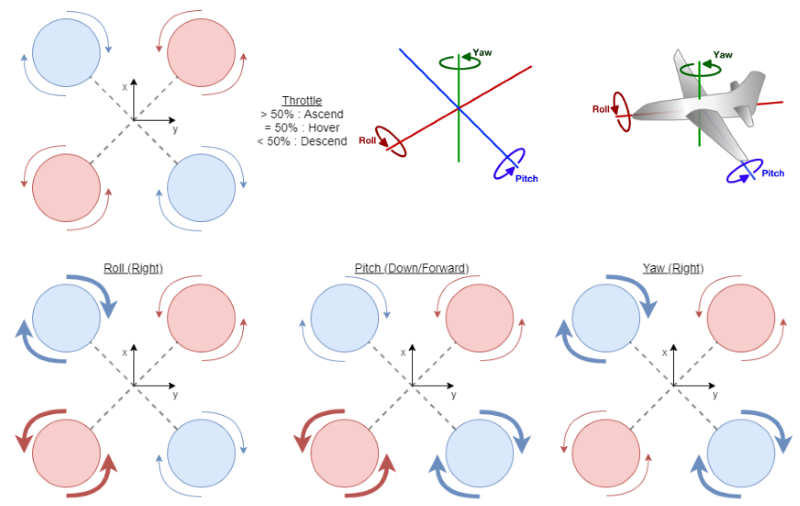
A quadcopter is a helipcopter with 4 rotors. One (diagonal) pair spins clockwise (CW), while the other pair spins counterclockwise (CCW). The movement of a quadcopter is controlled by varying the speed of the rotors.
The altitude of the quadcopter can be controlled by spinning all 4 rotors at the same angular velocity, such that the thrust generated is equal. In general, 2:1 is an acceptable thrust-to-weight ratio for a quadcopter, and allows the vehicle to hover at ~50% throttle.
The roll, pitch, and yaw of the quadcopter can be controlled by spinning 1 pair of rotors faster than the other pair.
Inertial Measurement Unit (IMU)
To control our quadcopter, we had to know where it is and what it’s doing. For our purposes, the combination of an accelerometer (which measures linear acceleration) and a gyroscope (which measures angular velocity) were sufficient to determine the orientation of our vehicle.
There are, however, some limitations due to the nature of these instruments. The accelerometer measures linear acceleration due to gravitional force to find the quadcopter’s position. But it also includes contribution from all other small forces, which introduces noise/disturbances to the reading. This makes accelerometer data more reliable for long-term measurements. On the other hand, the gyroscope measures angular velocity, and the position is found by integration over time. Due to a lack of positional reference, gyroscope data has a tendecy to drift from the origin when the data changes faster than the sampling frequency, making it only useful for short-term measurements.
While there are other methods (such as a Kalman filter) to address these issues, one of the easiest ways to make use of the advantages of both sensors is to use a complementary filter, which allows the accelerometer to help correct the drift of the gyroscope when calculating the current orientation.
RC System
Navigational commands are sent to the flight controller using a standard RC transmitter/receiver system. The position of the joysticks are converted to PWM (pulse-width modulated) signals, between 1k - 2k microseconds, which are received by the flight controller and reconverted to the corresponding value.
PID Controller
In order to control an inherently unstable system such as a quadcopter, a feedback controller is needed.
The Proportional + Integral + Derivative (PID) controller is a feedback controller that is often used to control a quadcopter. The PID controller can be viewed as a controller which takes into account the past, present, and future errors of the system, and is described mathematically by the following equation:
\[u(t)\ =\ K_pe(t)\ +\ K_i\int e(t) dt\ +\ K_p\frac{de}{dt},\]where \(u\) is the output of the PID controller/the control signal to the plant, \(e\) is the tracking error, \(K_p\) is the proportional gain, \(K_i\) is the integral gain, and \(K_d\) is the derivative gain.
The Proportional controller is a simple controller where the output is the product of the Proportional gain and the present error.
The Integral controller outputs the product of the Integral gain and the integral of previous errors.
The Derivative controller output is based on the derivative, or rate of change, of the error to estimate the future trend of the error.
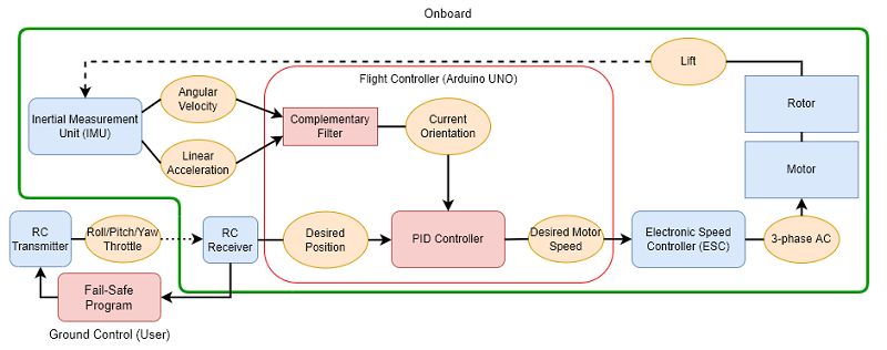
System Block Diagram
Hardware Design Process
Since none of us knew much about selecting quadcopter components, we began by looking into build kits. However, we quickly found that most of them were not only beyond our budget, but meant to be used with manufactured/pre-programmed flight controller chips, which would defeat the purpose of our project.
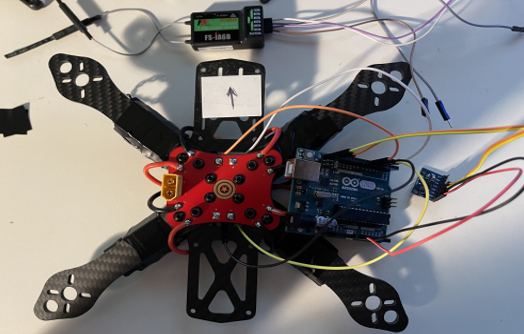
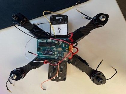
After further research, we made our initial purchases, which included a 220mm wheelbase carbon fiber frame (with 5030 propellers), a set of 2300kV brushless DC motors, electronic speed controllers, an MPU6050 IMU chip, a LiPo battery (+ charger), and a 6-channel digital radio control system.
Initial Testing and Design Adjustments
Upon assembling and testing our quadcopter, we found that it was too heavy! It took almost full throttle for our vehicle to start lifting, and it seemed off-balance. In our inexperience, we had neglected to properly account for the weight of all the components together! Oops. Going back to the drawing board, we decided to use a smaller battery, trading battery-life for less weight. We also opted for 3-blade propellers, which would help generate more lift.
Flight Controller Software
Among other tasks, I was in charge of the flight controller software. With no prior knowledge about flight controllers, I looked into all the open-source flight controllers I could find. The final version of our flight controller heavily references Project YMFC-AL by Joop Brokking, whose informative and well-documented code and process contributed greatly to our understanding and implementation of our own project. His code was used as a base for our flight controller program.
PID Tuning
With our hardware design finalized and our flight controller written, the final step was to tune, or determine the gain for, our PID controller. While there are various ways to design and tune a PID controller, most of them required having a model of the system available. Earlier in the design process, I had looked into whether it would be possible to determine a model for our system. However, after doing some research, including reading a few master’s thesis papers, I found that to properly model the quadcopter would require several measurements that we did not have the equipment to take. So it was decided that we would perform our PID tuning the way that it’s most commonly done for quadcopters: by trial and error.
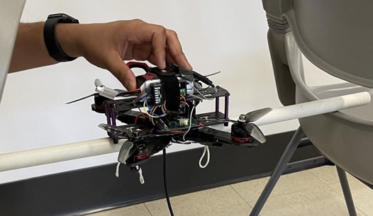
We tuned the controllers by adjusting the gain coefficients manually in the code, and observing their effects. One method that we implemented was by tying the quadcopter to a PVC pipe such that it was only able to rotate along one axis at a time.
Results and Analysis
By the deadline of our project, we had a mostly functioning quadcopter, but unfortunately it did not work perfectly.
There were two main issues that we ran into: Our quadcopter had a tendency to drift backwards, and it would sometimes unexpectedly “jump”, or greatly increase its altitude. We theorized that this was due to the mounting of the IMU chip on the quadcopter. Following some online tutorials, we had mounted the IMU onto the Arudino UNO using mounting putty. However, this caused the IMU to be misaligned with the body of the quadcopter. We believed that this constant error caused the Integral controller to overcompensate, resulting in a constant drift in the trajectory of the quadcopter. This likely also led to a phenomenon called “integral windup”, where accumulation of the integral error exceeds the saturation limit of the controller, which can lead to excessive overshooting, as seen in the “jumps” in altitude.
Unfortunately, we were not able to test our theory or remedy the design before the deadline, as a crash on our last testing day resulted in a broken wire to the power distribution board (PDB) which was not discovered until later.
Repository
The full code can be found in the repository here.