Analog-to-Digital / Digital-to-Analog Conversion using Arduino
Introduction
Part 2 of Benchtop Labs for Digital Control course.
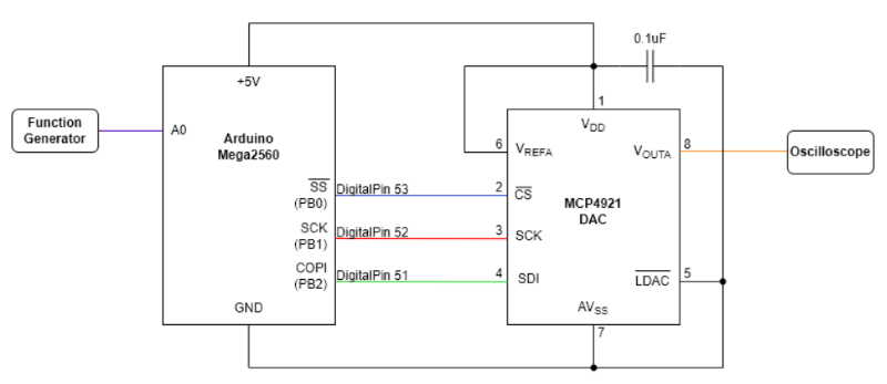
The purpose of this lab experiment is to understand the principals of analog-to-digital conversion (ADC) and digital-to-analog conversion (DAC). The system is implemented on an Arduino Mega2560. A sine wave from an external function generator serves as the analog input signal to the system. Analog-to-digital conversion is performed by the Arduino’s onboard ADC. The digital-to-analog process utilizes a MCP4921 IC chip. The resulting signal is outputted to an external oscilloscope in order to view the waveform. The effect of clock rate on the sampling process is also explored.
Project Overview
- Type: Individual
- Timeframe: Approx. 1 month
- Relevant Concepts/Skills: Research, component selection, analog circuit design, analog circuit testing, Arduino/C++ programming and debugging, analog-to-digital conversion (ADC), digital-to-analog conversion (DAC)
- Tools: Arduino IDE, Arduino Mega2560, digital function generator, digital multimeter (DMM), DC power supply, digital oscilloscope
- Deliverable(s): Physical circuit, demo, lab report
Procedures
- Assembled system circuit
- Converted analog input (sine wave) to digital signal using Arduino ADC
- Converted digital signal to analog output using MCP4921 IC chip (DAC)
- Increased clock rate and repeated procedures
System Block Diagram with Circuit Connections
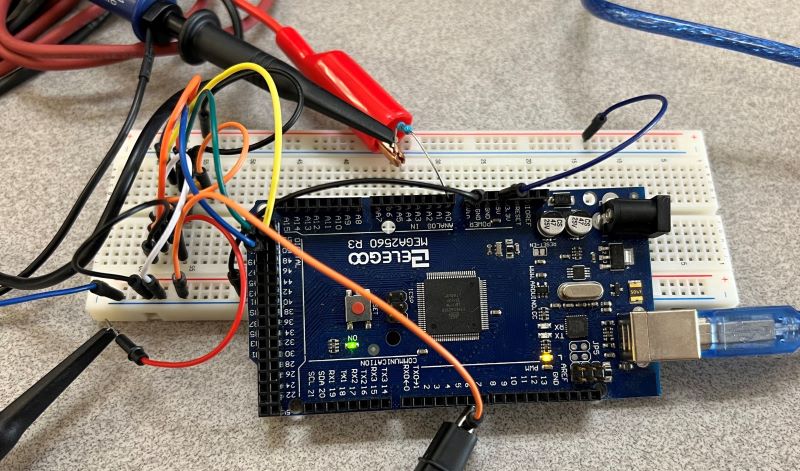
Physical Implementation
Results
Selected results are shown below. For the full results, please check out the details page.
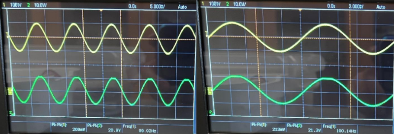
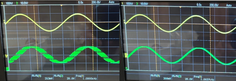
For all results, the default clock rate input/output is shown in the left, and the faster clock rate input/output is shown on the right. It should be noted that due to technical issues with the oscilloscope probes, the amplitude shown are not accurate. However, they were tested to be experimentally equivalent.
100Hz
1kHz
1kHz (paused)
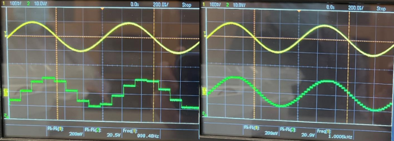
System was implemented properly and correctly converted analog input to digital signal, then back to analog output. The maximum input frequency at which the default clock rate is able to replicate the input sine wave is ≤ 1kHz, likely at a frequency closer to 100Hz. For the faster clock rate, the highest frequency appears to be around 2k - 5kHz.
Repository
The full code/repository can be found here.