Analog Lead Compensator Circuit
Introduction
Part 1 of Benchtop Labs for Digital Control course.
The purpose of this lab experiment is to model a satellite in the analog domain as a double integrator using op amps. As a double integrator is inherently unstable, an analog controller must be added to the system. In this experiment, a lead compensator is to be used as the controller for this system.
Project Overview
- Type: Individual
- Timeframe: Approx. 1 month
- Relevant Concepts/Skills: Research, component selection, analog circuit design, analog circuit testing, control theory, analog controller design, (lead) compensator, circuit simulation, operational amplifier (op-amp)
- Tools: Simulink, Cadence OrCAD PSPICE, digital function generator, digital multimeter (DMM), DC power supply, digital oscilloscope
- Deliverable(s): Physical circuit, demo, lab report
Procedures
- Selected components
- Designed circuit structure
- Designed lead compensator based on given transfer function
- Built Simulink model and simulated step response
- Built physical circuit and obtained step response
- Adjusted component values to optimize circuit: lower overshoot, decrease settling time
Results
Overall, the circuit worked as intended, but was very slow. This meant that the controller was only able to function at a very low frequency. It is possible that this was due to the fact that a single-supply op-amp was used.
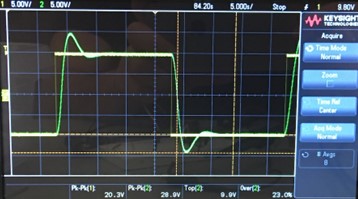
Rise time: ~2s
Settling time: ~7.5s
Percent overshoot: 23%
It should be noted that due to technical issues with the oscilloscope probes, the amplitude shown are ~10x the actual value.
Future Work
Though this analog circuit design fulfilled its overall purpose of implementing a double integrator plant, as well as a lead compensator to control the unstable double integrator signal, the slow speed of its response was a major deficiency, limiting the frequencies at which the circuit can serve its function. In future design iterations, changing from the use of single-supply op amps to dual-supply op amps could be a significant step towards improving the performance of the circuit.
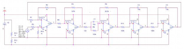
Full Schematic Diagram